Category: Tips

20 Apr 2018

Pockets Versus Assembly

In designing things it’s helpful to get an understanding of how those things are going to be made. In the past, designers used to be only a few walls away from manufacturing, so on the positive side, only a few strides were necessary to get some clarification on process, on the negative side, uninformed choices found you pretty quickly. Today, it’s a bit different. The locations of designers and manufacturers could be continents away.

At SCALAR we specialize in the less complex, more cost conscientious CNC fabrication projects where price can sometimes be the tightest tolerance aspect. Getting an understanding of price differentials in process can go a long way.

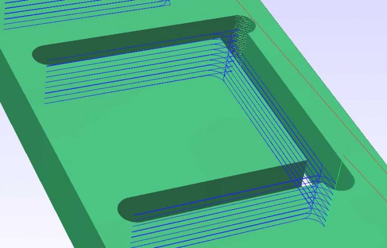
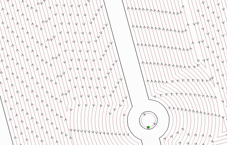
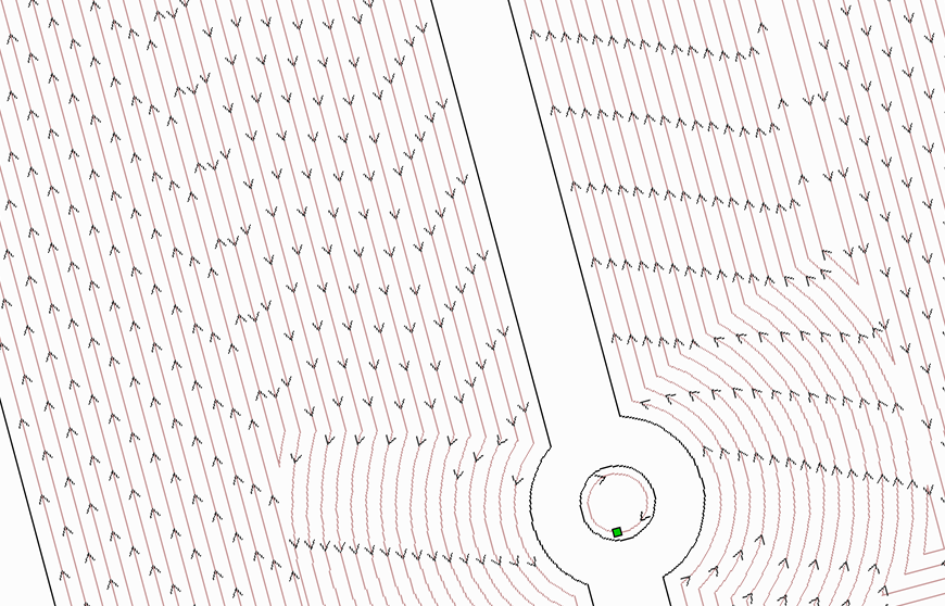
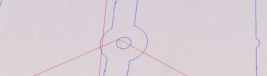
Today we’re going to look at pocketing – the process of removing material from an area but not cutting completely through. This can be necessary for a number of reasons: perhaps the product needs to fit over something else that cannot be changed, some routing / air gaps need to be added or maybe it would look that much cooler to have an indentation.

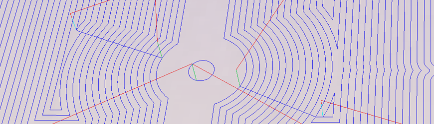
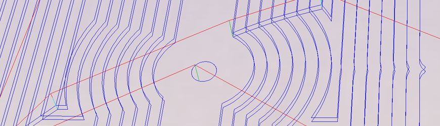
A fundamental component of pricing machined products is typically time. That doesn’t come as a shock, but time isn’t just how long the tool takes to cut through the material, it’s also set up cost and tool change cost, to name a few. Your nemesis is time and how you spend it. It’s good to know the options and what their time impact could be. For creating a pocket, one could, well, pocket the area, or one could through-cut two layers of material to achieve the pocket effect. We’ve taken a look at a recent job and ran the times between options to shed some light on pricing as it relates to choices. For this exercise, we’ve simplified the job by removing the redundant operations to focus on the pocketing decisions.

First up was one of the easier options for us: simply pocketing the area with the same bit as the through-cutting operation was using. In this instance, a ¼ inch end mill. The elapsed time for the pocketing is 1:25:42 That’s a really big – and expensive – number, but we don’t incur a tool change penalty in the process or have any extra assembly, either.

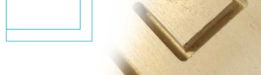
The next option was stepping up to a ½ inch end mill specifically for the pocketing operation. This drastically reduced the pocket time to 16:20. One thing to note is this requires a tool change. Depending on what equipment the manufacturer has, this could be a fractional cost or it could be a big deal if the manufacturer doesn’t rely on automated tool changing (then again, if the manufacturer does have these advanced setups, they’re probably handing off more fixed cost to your job – but that’s another post.) If the tool change takes 10 minutes, how much are you really saving?

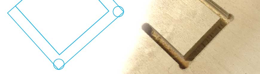
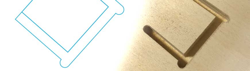
The last option we looked at was to split the job into layers where the pocketing becomes a through-cut. The time cutting out the pocket took 8:51.  This time was the quickest of all and didn’t require a tool change operation. Somewhere down the road, the two layers will have to be assembled and that carries cost, as well. If the component is destined to be assembled anyhow, maybe the cost isn’t as much of an adder.

While there certainly isn’t a correct answer for everyone, we think it’s interesting to math out the options and use that as a guide in developing what’s the best strategy for manufacturing.

Naturally, if you have any questions or would like to discuss possible options further, please feel free to contact us!


12 Sep 2017

Cornering in CNC cutting

Cutting inside corners with CNC fabrication machines can be a bit tricky. Here are a few possible solutions.


We’re what’s known principally as a 2.5D fabrication company. I’m not completely sure what that means. Is that because a knee mill has a deeper Z? Or that we focus on sheet stock material? I don’t know, but what I do know is that we tend to deal with corner cutting quite a bit as it relates to the inevitable fitting of squares into circles. More specifically, the finishing of radiused inside corners. I’m sure most machining centers do as well, despite having that extra 0.5D at the ready.

To illustrate a few of the possible solutions, we took a bit of machine time to quickly cut examples in real wood. By ‘quickly,’ we really mean quick and dirty as time didn’t permit dialing in the machine or finish sanding.

Everyone wants that perfect square inside corner in their work – maybe because it just looks crisp or perhaps they have what amounts to a tenon to fit in there. The round tooling every shop uses can’t accommodate that desire. It can get close, but you eventually end up with a radius on the inner corner like above. The smaller the bit, the less egregious the radius to be sure. With this in mind, a possible answer to the mated part issue is to simply put an outside radius on the tenon. Sometimes that’s just not in the plan.

But what are the other options? We could pick a few ways to overshoot the corner.

Pre-drilling the corners yields a corner like this. It makes room for the corners of the mated piece. If you set it up like the above drawing to the above left, you can minimize the excess of material removal. The downside is that it performs one more distinct operation in the process. It takes a bit more time and when you get charged for time on the machine it can make a difference if the volume is great enough.


Another option is to actually overshoot the corner of the rectangle. This way the excess corner material is taken out using the same tool path as the cutting of the shape. For the CNC purists it also is a bit easier on the cutting tool as the bit doesn’t perform the unsatisfactory slow to stop/direction change as seen in the radiused corners which could end up burning the work piece. The trade-off is they tend to take a bit more attention to hide in the design of the product’s assembly.

Both of these options obviously wouldn’t pass muster with classically-trained, chisel-wielding craftsmen. But then again if you make the adjustment, we can cut you a number of work pieces before any of those craftsmen can sharpen their chisels! It’s all in the design, specification and the expectations of the job. Without that specification, we’ll default to that inner radius.

04 Nov 2016

Digital Joints for Woodworking

A while ago I came across this totally excellent post on ArchDaily on a professor and designer at Hochschule für Gestaltung Offenbach in Germany who had put together what I figure as the thus-far definitive archive of joints and joinery designed expressly for digital manufacture. I’ve not gone through the entire archive of material  – as it certainly seems exhaustive and precise. I’d suggest you follow the link and download the archive before this gem gets lost to the sands of time!

Oh and show some love to ArchDaily for posting. Hopefully they’ll find even more great content in this vein!