16 Jul 2025

Infill needs to be designed in CAD, not in the slicer

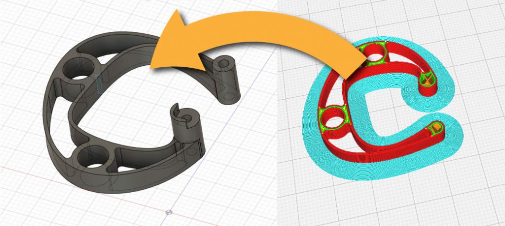
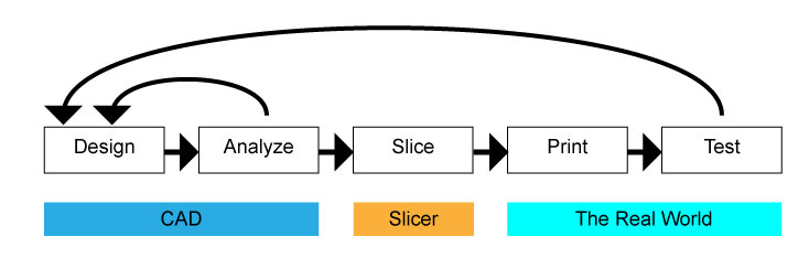
While there are others working on something more integrated, for everyone else the part design and 3D printing process is a two step affair: design the part in some CAD software suite then export the part to a slicer to create the file needed to print. The first step is where the outer aspects of the part are developed – the overall shape and the features of the part, etc. The second step is where the features the 3D printing process needs to be successful are developed – including the layer counts, the configuration of the part within the printer and the infill.

Today’s design-to-print tool chain rendered obviously crudely. The diagram still explains the hard truths that a lot of double work is being done to get to a workable solution, especially for high performance parts.

It’s obvious why this division of operations developed the way it has. In the beginning, CAD software was built for subtractive operations and at the time it had virtually no functionality for printing items. The additive community had to develop software to translate the CAD files into the gCode to operate on the then nascent technology. That created the process of making your shapes in CAD, exporting it to a file that could be loaded into that specialized 3D printer file, a slicer, to be transformed into the required gCode.

The above was perfectly fine for getting the 3D printing industry started by making a complex process relatively easy to perform. Now, we live in the future. 

In order for 3D printing to really make an impact, it needs to have software built to take advantage of the process. That means we need to have the right processes in the correct stage of the design-print chain. We need to have infill selection, configuration and design in the CAD side of things.

For now

Why? The reason is the infill helps provide the mechanical characteristics of the material used and the designed shapes themselves. The infill helps determine the strength of the part, the mass of the part and perhaps even the flexibility, distribution of said mass and perhaps even characteristics of heat dissipation and other advanced aspects. 

If the designer is relying on the CAD software to provide some of these calculations – either through the basic functionality of the CAD suite itself or exporting models to more advanced analysis tools, those numbers will be based on a solid material, rather than a lattice material within a shell casing. In short, the numbers will not correspond to the printed part. Perhaps this might not be much of an issue for lightweight plastic not being called into service on something high performance, but for metals, it can be an issue. What’s more, this separation of infill and design disallows designers to truly maximize material usage because the testing is well before and completely disconnected from the slicing stage. The designer will have to over-engineer a part just to make sure it operates properly, or rely on testing of the printed part afterwards to dial in the infill and sometimes even the designed shape’s characteristics to guarantee proper functionality.

For the future

While this crude diagram does not show potential revisions after testing, moving the analysis after the slicing will help reduce the amount of aforementioned double work by analyzing the part actually being printed.

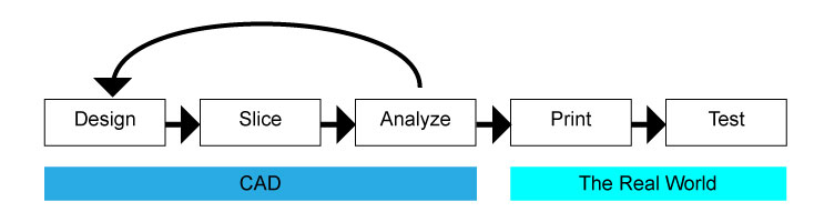
If we really want to capitalize from the capability of Additive Manufacturing, then that will only come from having complete design authority over the part at the design stage. Moving infill into the design stage opens opportunities to begin thinking about the advantages of being able to tune the infill for specific tasks. 

With the right tools, designers can push infill from a homogeneous pattern into ones that integrate the part’s use case – from the inside out. The pattern could change and become more dense in certain areas and directions where it is critically needed and significantly lessened where it is only marginally needed. Perhaps the infill pattern could be designed in such a way that it could allow flexibility in one direction and high rigidity in another according to the conditions the part needs to operate in. Maybe the infill could be designed to absorb or even channel heat within the part more effectively.

While the above are just a few examples, they quickly highlight the potential that could be unlocked when infill is designed within the part development process rather than purely considered a function of gCode construction.

14 Feb 2025

What if 3D printing is actually held back by CAD?

There are signs everywhere that point to the end of forward motion in additive manufacturing. There’s the business consolidations, the re-calculation of value, and perhaps most telling is the seeming slow down in printing innovation. We’ve also seen a reduction in novel uses and new markets for 3D printing – or at least it feels like it is from its peak five years ago. All these aspects make it easy to say additive has achieved everything it could.

But what if that’s the wrong take?

After being around various areas of the 3D printing universe, I think what we are seeing is completely different. As the title says, it is not 3D printing that is stalling of its own accord, it is stalling because of technology upstream of the process – CAD.

When this whole additive thing started taking off, the world was awash in possibilities that could be achieved with these processes. There would be alien-shaped structures that would be super efficient in operation and in material use. We would see vast reduction in part counts, as entire assemblies could be combined. Heretofore unbuildable fluid management systems whose complex passageways could never be cast, much less machined. It went on and on, almost faster than imagination could take us.

The reality turned out much different. Aside from some proof of concepts, many of these prognostications have never made it into the world – and certainly nowhere near the pervasiveness we all dreamed of. 

The question is: Why not? The answer is not that the additive technology isn’t there to do it. The answer may be the software is not widely available or anywhere near easy to operate to design this complexity for the process. 

We were looking for something like this…

Many of the truly novel designs printed have been created where the designer had to perform at least some degree of manual coding to pull off the feat – either writing complex code for custom software that designed the shape and output the gCode or taking the ‘easy’ way out and using (or abusing?) an off-the-shelf design package’s own coding platform, like Rhino’s Grasshopper, Python in Blender or forcing Creo to operate on point clouds or some other process that forces the software to go where it is not designed to go. 

Whatever the method, it was certainly not easy – those shapes are not what current CAD packages are designed to do well. That’s because today’s CAD packages are designed expressly for subtractive processes, and they do that very, very well. That mastery comes at the cost of doing other things well, especially utilizing additive’s capabilities.

…but we’re kind of stuck here.

Of course, the issue is even more pervasive than the lack of software to bring out the best in 3D printing. The designers who all have learned how to create things have also gotten extraordinarily good at operating the current software. That happens through mastering the subtractive design paradigm.  Even if the software were to change a few years ago (here’s looking at you Autodesk Fusion360 Generative), additive would still have to wait until the subtractive mindset is changed in the design and engineering workforce. 

At this moment, I do not have a solution, aside from developing design software purpose-built to take advantage of what additive can do. Frankly, being one of those trained in the subtractive ways, even visualizing how additive-first design software would behave is just as difficult as trying to get your head around eating a hot fudge sundae from the inside out. 

Meanwhile, all these 3D printers are still waiting to do their best work – or at least the work they were designed to do. That means waiting for CAD to catch up.

02 Oct 2022

Designing for 3D printing – thinking of print speed

Slicing in Cura

There’s a lot a designer or engineer needs to keep in mind while designing parts. Functionality is obviously paramount. Manufacturability is right behind making sure it works. 

When you strip away the powder-based processes, designing for manufacturability can move into places that many designers and engineers haven’t properly considered – especially when that part needs to have a large quantity made through 3D printing or if the part is large. 

Many will yawn about making sure overhangs and degrees of precision between competing processes are accounted for but there’s something else that should be considered: the time needed to make the part. That time per part originates in how the part was designed. 

A great engineer who designs for parts via CNC knows that they have to not only keep track of how many different kinds and sizes of tooling is needed, they also have to be cognizant of how a tool will travel and interact with the workpiece. This will have a direct impact on the cost of the part. This thinking must be extended to non-powder 3D processes as well. The biggest area ignored and perhaps one of the most important is working to keep the print head moving efficiently as possible in the least amount of time. 

I think most of us are used to designing in solid modeling software. That means we’re used to thinking of carving the shape to get what we need – because the software is made to primarily develop parts for conventional subtractive processes. That thinking doesn’t get the most out of additive processes. To illustrate this, I needed to develop a bracket for a sensor. My usual solid block carving process would end up here:

Sure, this could be printed, but maybe we should be designing differently from the very start for an additive solution. Below is my first pass at thinking more additively:

In this process, I started with the absolutely necessary aspects. I needed to position the sensor board in a specific orientation and secure it using the provided holes. The sensor also needed to be connected to the machine and clocked in a certain direction using provided screws and locations. From here, I worked to connect all of these features with material that would be enough to hold all in place. The material was also my best estimate of the most efficient paths for the printer to follow. 

What did I get for my effort? Here’s the estimated time directly from Cura for the block-based approach:

The second process looked like this with the same slicer settings: 

Admittedly, this is a small part, so the time savings is only 17 minutes. When you look at the percentage of time saved, it shakes out to a 40% reduction in total print time. And that’s without messing with esoteric slicer settings and machine speeds. 

If the part took 8 hours to print, that 40% becomes a big deal. It also becomes a big deal when there needs to be a large quantity of parts printed. Because what’s similar between making parts on a subtractive machine and an additive machine is cost is based primarily on time-on-machine.

07 Jun 2018

Is Surface Finish Really a Concern for 3D Printing?

It seems the surface finish of 3D printed parts continues to be a pretty big deal, especially in FDM printing. Let’s be a bit more specific about finish and aim at the aesthetic aspects while setting aside functional issues regarding finish.

Back in college, I wrote a little opinion piece about the seeming draw of – or at least ambivalence to – contemporary shoppers to faux finishes. Everything from hubcaps to fake plants were used to support the notion. While the argument might be fun to rehash, today we could easily feel comfortable saying most of us are really not aghast of materials aping other materials. We’ve become comfortable to the point where we don’t even consider that the surface finishes in our cars are supposed to be approximations of more expensive materials like leather or wood represented in plastic. We’ve also have allowed veneering to uplift substandard materials in our furniture – and even have looked a blind eye to now using plastic-based, printed veneer to take the place of real, natural veneers. The feel of Formica and Corian is just as common and accepted as marble countertops and sometimes preferred.

These previously aesthetically abhorrent finishes are now pretty much commonplace. My question here is will we really have to worry about the mechanical finishes of most 3D printing methods, or will these finishes eventually become canon in the landscape of the near future?

3D printing gives a lot of fabrication opportunities previously only dreamed of. There’s the possibility of new shapes as well as more mundane aspects like manufacture-ability and eventually leading to mass customization. Will the value of the ability to quickly manufacture a bespoke item offset the surface finish from the process? Would we be good with that?

Basically that trade off is the same proposition that whichever movement you’d like to use, be it Art Deco or International Style Modernism gave us at the turn of the previous century – or even the big three with hubcaps that look like expensive cast wheels.

Would you desire something so much you’re willing to give up some detail to get it? If history is a roadmap for the future, the answer is yes.


20 Apr 2018

Pockets Versus Assembly

In designing things it’s helpful to get an understanding of how those things are going to be made. In the past, designers used to be only a few walls away from manufacturing, so on the positive side, only a few strides were necessary to get some clarification on process, on the negative side, uninformed choices found you pretty quickly. Today, it’s a bit different. The locations of designers and manufacturers could be continents away.

At SCALAR we specialize in the less complex, more cost conscientious CNC fabrication projects where price can sometimes be the tightest tolerance aspect. Getting an understanding of price differentials in process can go a long way.

Today we’re going to look at pocketing – the process of removing material from an area but not cutting completely through. This can be necessary for a number of reasons: perhaps the product needs to fit over something else that cannot be changed, some routing / air gaps need to be added or maybe it would look that much cooler to have an indentation.

A fundamental component of pricing machined products is typically time. That doesn’t come as a shock, but time isn’t just how long the tool takes to cut through the material, it’s also set up cost and tool change cost, to name a few. Your nemesis is time and how you spend it. It’s good to know the options and what their time impact could be. For creating a pocket, one could, well, pocket the area, or one could through-cut two layers of material to achieve the pocket effect. We’ve taken a look at a recent job and ran the times between options to shed some light on pricing as it relates to choices. For this exercise, we’ve simplified the job by removing the redundant operations to focus on the pocketing decisions.

First up was one of the easier options for us: simply pocketing the area with the same bit as the through-cutting operation was using. In this instance, a ¼ inch end mill. The elapsed time for the pocketing is 1:25:42 That’s a really big – and expensive – number, but we don’t incur a tool change penalty in the process or have any extra assembly, either.

The next option was stepping up to a ½ inch end mill specifically for the pocketing operation. This drastically reduced the pocket time to 16:20. One thing to note is this requires a tool change. Depending on what equipment the manufacturer has, this could be a fractional cost or it could be a big deal if the manufacturer doesn’t rely on automated tool changing (then again, if the manufacturer does have these advanced setups, they’re probably handing off more fixed cost to your job – but that’s another post.) If the tool change takes 10 minutes, how much are you really saving?

The last option we looked at was to split the job into layers where the pocketing becomes a through-cut. The time cutting out the pocket took 8:51.  This time was the quickest of all and didn’t require a tool change operation. Somewhere down the road, the two layers will have to be assembled and that carries cost, as well. If the component is destined to be assembled anyhow, maybe the cost isn’t as much of an adder.

While there certainly isn’t a correct answer for everyone, we think it’s interesting to math out the options and use that as a guide in developing what’s the best strategy for manufacturing.

Naturally, if you have any questions or would like to discuss possible options further, please feel free to contact us!


13 Apr 2018

Industrial Control Panel

Project: Industrial Control Panel

Material: Expanded PVC

This production of 20 panels was designed for use as a mounting point for several industrial switches that constitute the control points of a custom machine, including the primary power switch, machine on, machine stop and an emergency safety switch. The switches and status LEDs are screw mounted to the board. The board itself is designed to be screwed to the main panel via fasteners through the corner holes on the mounting panel.

12 Sep 2017

Cornering in CNC cutting

Cutting inside corners with CNC fabrication machines can be a bit tricky. Here are a few possible solutions.


We’re what’s known principally as a 2.5D fabrication company. I’m not completely sure what that means. Is that because a knee mill has a deeper Z? Or that we focus on sheet stock material? I don’t know, but what I do know is that we tend to deal with corner cutting quite a bit as it relates to the inevitable fitting of squares into circles. More specifically, the finishing of radiused inside corners. I’m sure most machining centers do as well, despite having that extra 0.5D at the ready.

To illustrate a few of the possible solutions, we took a bit of machine time to quickly cut examples in real wood. By ‘quickly,’ we really mean quick and dirty as time didn’t permit dialing in the machine or finish sanding.

Everyone wants that perfect square inside corner in their work – maybe because it just looks crisp or perhaps they have what amounts to a tenon to fit in there. The round tooling every shop uses can’t accommodate that desire. It can get close, but you eventually end up with a radius on the inner corner like above. The smaller the bit, the less egregious the radius to be sure. With this in mind, a possible answer to the mated part issue is to simply put an outside radius on the tenon. Sometimes that’s just not in the plan.

But what are the other options? We could pick a few ways to overshoot the corner.

Pre-drilling the corners yields a corner like this. It makes room for the corners of the mated piece. If you set it up like the above drawing to the above left, you can minimize the excess of material removal. The downside is that it performs one more distinct operation in the process. It takes a bit more time and when you get charged for time on the machine it can make a difference if the volume is great enough.


Another option is to actually overshoot the corner of the rectangle. This way the excess corner material is taken out using the same tool path as the cutting of the shape. For the CNC purists it also is a bit easier on the cutting tool as the bit doesn’t perform the unsatisfactory slow to stop/direction change as seen in the radiused corners which could end up burning the work piece. The trade-off is they tend to take a bit more attention to hide in the design of the product’s assembly.

Both of these options obviously wouldn’t pass muster with classically-trained, chisel-wielding craftsmen. But then again if you make the adjustment, we can cut you a number of work pieces before any of those craftsmen can sharpen their chisels! It’s all in the design, specification and the expectations of the job. Without that specification, we’ll default to that inner radius.

17 Jun 2017

Thinking savvy about CNC cutting

I happened across the TED ELEVATE warming huts project by Design Build Research institute.  The arches play such a large role in defining not just the structure but the aesthetic of the structure. For someone who looks at projects like this from the fabrication perspective, components like these arches also constitute the largest amount of challenges, especially when trying to control for cost.

With the CNC process, the largest amount of cost comes from is time on machine. Put simply, the more a machine has to cut the more expensive things are. These arches are wonderfully thick so that presents two issues, one is time it takes the CNC machine to profile through the individual thickness of the workpiece. This is exasperated by the notion that there’s a few layers of individual work pieces needed to complete each arch. I’d also think that the overall shape and scale of the arches would have impact on the number of components needed to be cut.

That introduces a third area where costs originate – unloading and resetting the machine. While the machine isn’t generating income there, the people needed to do the switching of work pieces start generating costs. That cost doubles with successive arch layers. The shape of the arch also plays a part here by deciding the ability to extract as many pieces per workpiece as possible. If the job can only fit one component per work piece then there’ll be more costs associated with resetting the machine.

Obviously, all this really doesn’t have that much effect on smaller projects but when there’s large components and larger quantities like the ones needed for these shells, these sorts of things tend to start adding up rather quickly.

It’s interesting to talk about these aspects as it relates to the design of the structure. In the manufacturing world they call this engineering for manufacturing. In that world, the big shift is to engage manufacturing engineers who work to efficiently produce products well before the process of designing the product is complete. Perhaps this sort of thinking could also be useful for the more complex structures that can be now available with the preponderance of CNC machining available to architects and designers.

Knowing where costs come from in this relatively nascent market might go a long way to making more exciting things that much more achievable.

09 May 2017

Electronic Device Panel

Project: Electronic Device Panel

Material: ABS

A control panel designed for a heavy duty product with electronic controls. Production run intended to bridge between initial product production and when high-volume component production comes online. The switches and LED panel are designed to be press-fit into the ABS material and the entire component group adhered to the product.

26 Apr 2017

Clemson’s Novel Construction Details

One of the big draws of using a great deal of CNC cut materials in the construction of structures has been the prospect of integrating the the interconnection of components into the components themselves. A few of the previous system attempts at building structures completely from CNC cut plywood have focused on some sort of tab principle to sidestep conventional mechanical fastening like screws or nails. This system offered by Clemson University has used something a bit different – the use of zip-ties to serve the inevitable need for fastening beyond the tab or friction-fit concept.

I’m still getting my head around the methods, processes and design elements necessary to carry this off. I’d assume that the integration of zip-tie fastening would actually be rather easy to do. Slithering plastic ties through wood components would really only require the placement of through holes at the right areas. That seems deliciously easy. In my mind, the tricky part would be to route the ties through in a manner where their best features are used in the strongest manner.

Thinking about zip ties, I’d figure that their strength lies in tensile loading and twisting forces. The weaknesses would be the fact that their flexibility would be difficult to mitigate when trying to get rigidity out of the connections. Perhaps this could be addressed in the remainder of the wood connection design where there isn’t sufficient directional latitude for the twisting to happen?

To this end, there seems to be painfully little imagery published of Clemson’s zip tie system to get an idea on how this system would be executed. Hopefully in the future, the university will mete out a bit more detail. Until then, I guess it’s back to the labs and the sketchbooks to try and arrive at how it could all work!