Year: 2018

07 Jun 2018

Is Surface Finish Really a Concern for 3D Printing?

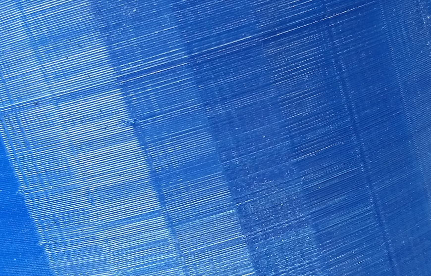
It seems the surface finish of 3D printed parts continues to be a pretty big deal, especially in FDM printing. Let’s be a bit more specific about finish and aim at the aesthetic aspects while setting aside functional issues regarding finish.

Back in college, I wrote a little opinion piece about the seeming draw of – or at least ambivalence to – contemporary shoppers to faux finishes. Everything from hubcaps to fake plants were used to support the notion. While the argument might be fun to rehash, today we could easily feel comfortable saying most of us are really not aghast of materials aping other materials. We’ve become comfortable to the point where we don’t even consider that the surface finishes in our cars are supposed to be approximations of more expensive materials like leather or wood represented in plastic. We’ve also have allowed veneering to uplift substandard materials in our furniture – and even have looked a blind eye to now using plastic-based, printed veneer to take the place of real, natural veneers. The feel of Formica and Corian is just as common and accepted as marble countertops and sometimes preferred.

These previously aesthetically abhorrent finishes are now pretty much commonplace. My question here is will we really have to worry about the mechanical finishes of most 3D printing methods, or will these finishes eventually become canon in the landscape of the near future?

3D printing gives a lot of fabrication opportunities previously only dreamed of. There’s the possibility of new shapes as well as more mundane aspects like manufacture-ability and eventually leading to mass customization. Will the value of the ability to quickly manufacture a bespoke item offset the surface finish from the process? Would we be good with that?

Basically that trade off is the same proposition that whichever movement you’d like to use, be it Art Deco or International Style Modernism gave us at the turn of the previous century – or even the big three with hubcaps that look like expensive cast wheels.

Would you desire something so much you’re willing to give up some detail to get it? If history is a roadmap for the future, the answer is yes.


20 Apr 2018

Pockets Versus Assembly

In designing things it’s helpful to get an understanding of how those things are going to be made. In the past, designers used to be only a few walls away from manufacturing, so on the positive side, only a few strides were necessary to get some clarification on process, on the negative side, uninformed choices found you pretty quickly. Today, it’s a bit different. The locations of designers and manufacturers could be continents away.

At SCALAR we specialize in the less complex, more cost conscientious CNC fabrication projects where price can sometimes be the tightest tolerance aspect. Getting an understanding of price differentials in process can go a long way.

Today we’re going to look at pocketing – the process of removing material from an area but not cutting completely through. This can be necessary for a number of reasons: perhaps the product needs to fit over something else that cannot be changed, some routing / air gaps need to be added or maybe it would look that much cooler to have an indentation.

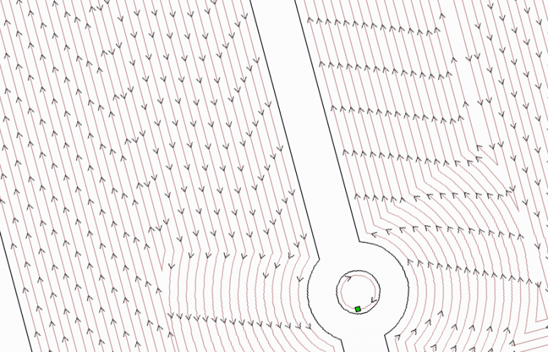
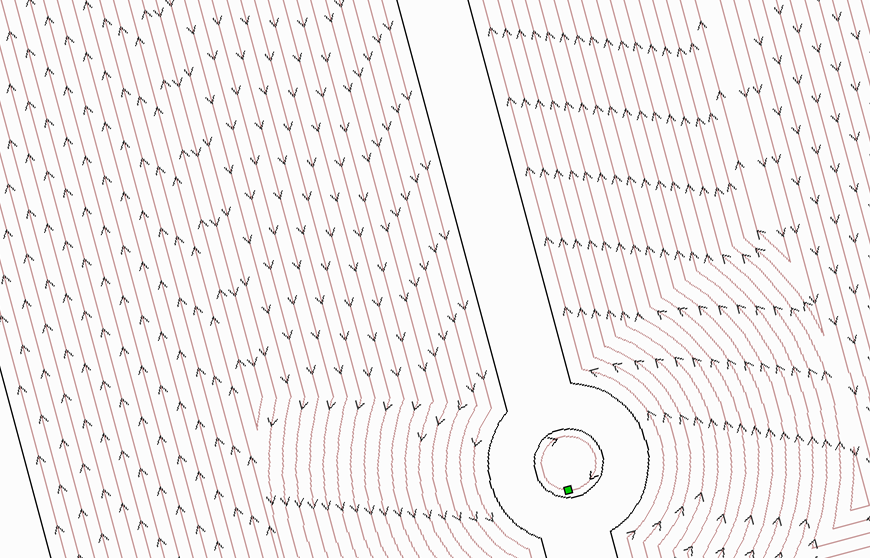
A fundamental component of pricing machined products is typically time. That doesn’t come as a shock, but time isn’t just how long the tool takes to cut through the material, it’s also set up cost and tool change cost, to name a few. Your nemesis is time and how you spend it. It’s good to know the options and what their time impact could be. For creating a pocket, one could, well, pocket the area, or one could through-cut two layers of material to achieve the pocket effect. We’ve taken a look at a recent job and ran the times between options to shed some light on pricing as it relates to choices. For this exercise, we’ve simplified the job by removing the redundant operations to focus on the pocketing decisions.

First up was one of the easier options for us: simply pocketing the area with the same bit as the through-cutting operation was using. In this instance, a ¼ inch end mill. The elapsed time for the pocketing is 1:25:42 That’s a really big – and expensive – number, but we don’t incur a tool change penalty in the process or have any extra assembly, either.

The next option was stepping up to a ½ inch end mill specifically for the pocketing operation. This drastically reduced the pocket time to 16:20. One thing to note is this requires a tool change. Depending on what equipment the manufacturer has, this could be a fractional cost or it could be a big deal if the manufacturer doesn’t rely on automated tool changing (then again, if the manufacturer does have these advanced setups, they’re probably handing off more fixed cost to your job – but that’s another post.) If the tool change takes 10 minutes, how much are you really saving?

The last option we looked at was to split the job into layers where the pocketing becomes a through-cut. The time cutting out the pocket took 8:51.  This time was the quickest of all and didn’t require a tool change operation. Somewhere down the road, the two layers will have to be assembled and that carries cost, as well. If the component is destined to be assembled anyhow, maybe the cost isn’t as much of an adder.

While there certainly isn’t a correct answer for everyone, we think it’s interesting to math out the options and use that as a guide in developing what’s the best strategy for manufacturing.

Naturally, if you have any questions or would like to discuss possible options further, please feel free to contact us!


13 Apr 2018

Industrial Control Panel

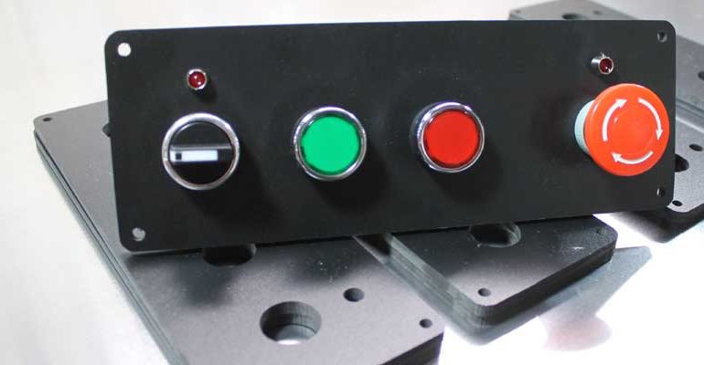
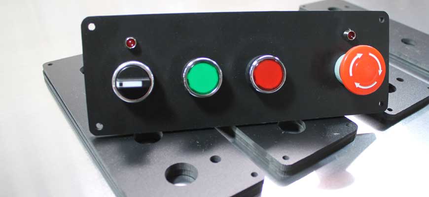
Project: Industrial Control Panel

Material: Expanded PVC

This production of 20 panels was designed for use as a mounting point for several industrial switches that constitute the control points of a custom machine, including the primary power switch, machine on, machine stop and an emergency safety switch. The switches and status LEDs are screw mounted to the board. The board itself is designed to be screwed to the main panel via fasteners through the corner holes on the mounting panel.