Year: 2017

12 Sep 2017

Cornering in CNC cutting

Cutting inside corners with CNC fabrication machines can be a bit tricky. Here are a few possible solutions.


We’re what’s known principally as a 2.5D fabrication company. I’m not completely sure what that means. Is that because a knee mill has a deeper Z? Or that we focus on sheet stock material? I don’t know, but what I do know is that we tend to deal with corner cutting quite a bit as it relates to the inevitable fitting of squares into circles. More specifically, the finishing of radiused inside corners. I’m sure most machining centers do as well, despite having that extra 0.5D at the ready.

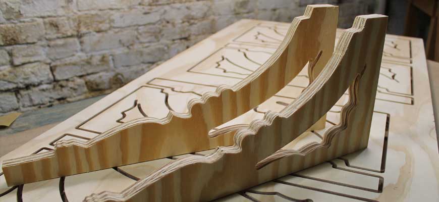
To illustrate a few of the possible solutions, we took a bit of machine time to quickly cut examples in real wood. By ‘quickly,’ we really mean quick and dirty as time didn’t permit dialing in the machine or finish sanding.

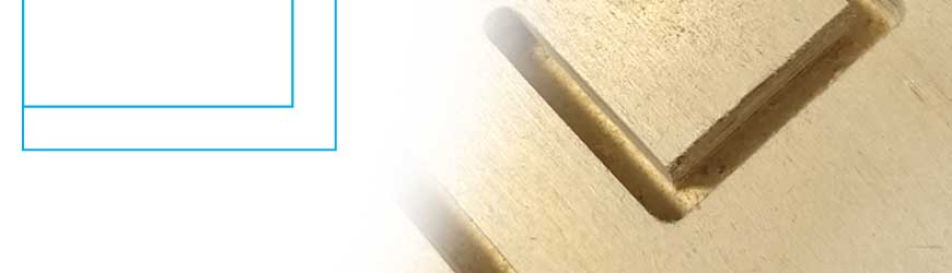
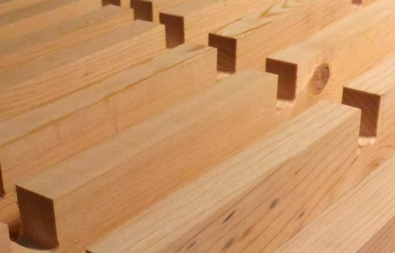
Everyone wants that perfect square inside corner in their work – maybe because it just looks crisp or perhaps they have what amounts to a tenon to fit in there. The round tooling every shop uses can’t accommodate that desire. It can get close, but you eventually end up with a radius on the inner corner like above. The smaller the bit, the less egregious the radius to be sure. With this in mind, a possible answer to the mated part issue is to simply put an outside radius on the tenon. Sometimes that’s just not in the plan.

But what are the other options? We could pick a few ways to overshoot the corner.

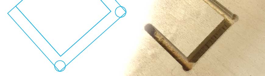
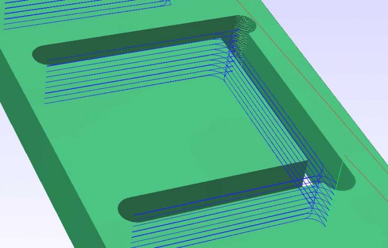
Pre-drilling the corners yields a corner like this. It makes room for the corners of the mated piece. If you set it up like the above drawing to the above left, you can minimize the excess of material removal. The downside is that it performs one more distinct operation in the process. It takes a bit more time and when you get charged for time on the machine it can make a difference if the volume is great enough.


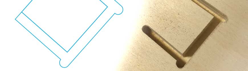
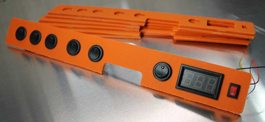
Another option is to actually overshoot the corner of the rectangle. This way the excess corner material is taken out using the same tool path as the cutting of the shape. For the CNC purists it also is a bit easier on the cutting tool as the bit doesn’t perform the unsatisfactory slow to stop/direction change as seen in the radiused corners which could end up burning the work piece. The trade-off is they tend to take a bit more attention to hide in the design of the product’s assembly.

Both of these options obviously wouldn’t pass muster with classically-trained, chisel-wielding craftsmen. But then again if you make the adjustment, we can cut you a number of work pieces before any of those craftsmen can sharpen their chisels! It’s all in the design, specification and the expectations of the job. Without that specification, we’ll default to that inner radius.

17 Jun 2017

Thinking savvy about CNC cutting

I happened across the TED ELEVATE warming huts project by Design Build Research institute.  The arches play such a large role in defining not just the structure but the aesthetic of the structure. For someone who looks at projects like this from the fabrication perspective, components like these arches also constitute the largest amount of challenges, especially when trying to control for cost.

With the CNC process, the largest amount of cost comes from is time on machine. Put simply, the more a machine has to cut the more expensive things are. These arches are wonderfully thick so that presents two issues, one is time it takes the CNC machine to profile through the individual thickness of the workpiece. This is exasperated by the notion that there’s a few layers of individual work pieces needed to complete each arch. I’d also think that the overall shape and scale of the arches would have impact on the number of components needed to be cut.

That introduces a third area where costs originate – unloading and resetting the machine. While the machine isn’t generating income there, the people needed to do the switching of work pieces start generating costs. That cost doubles with successive arch layers. The shape of the arch also plays a part here by deciding the ability to extract as many pieces per workpiece as possible. If the job can only fit one component per work piece then there’ll be more costs associated with resetting the machine.

Obviously, all this really doesn’t have that much effect on smaller projects but when there’s large components and larger quantities like the ones needed for these shells, these sorts of things tend to start adding up rather quickly.

It’s interesting to talk about these aspects as it relates to the design of the structure. In the manufacturing world they call this engineering for manufacturing. In that world, the big shift is to engage manufacturing engineers who work to efficiently produce products well before the process of designing the product is complete. Perhaps this sort of thinking could also be useful for the more complex structures that can be now available with the preponderance of CNC machining available to architects and designers.

Knowing where costs come from in this relatively nascent market might go a long way to making more exciting things that much more achievable.

09 May 2017

Electronic Device Panel

Project: Electronic Device Panel

Material: ABS

A control panel designed for a heavy duty product with electronic controls. Production run intended to bridge between initial product production and when high-volume component production comes online. The switches and LED panel are designed to be press-fit into the ABS material and the entire component group adhered to the product.

26 Apr 2017

Clemson’s Novel Construction Details

One of the big draws of using a great deal of CNC cut materials in the construction of structures has been the prospect of integrating the the interconnection of components into the components themselves. A few of the previous system attempts at building structures completely from CNC cut plywood have focused on some sort of tab principle to sidestep conventional mechanical fastening like screws or nails. This system offered by Clemson University has used something a bit different – the use of zip-ties to serve the inevitable need for fastening beyond the tab or friction-fit concept.

I’m still getting my head around the methods, processes and design elements necessary to carry this off. I’d assume that the integration of zip-tie fastening would actually be rather easy to do. Slithering plastic ties through wood components would really only require the placement of through holes at the right areas. That seems deliciously easy. In my mind, the tricky part would be to route the ties through in a manner where their best features are used in the strongest manner.

Thinking about zip ties, I’d figure that their strength lies in tensile loading and twisting forces. The weaknesses would be the fact that their flexibility would be difficult to mitigate when trying to get rigidity out of the connections. Perhaps this could be addressed in the remainder of the wood connection design where there isn’t sufficient directional latitude for the twisting to happen?

To this end, there seems to be painfully little imagery published of Clemson’s zip tie system to get an idea on how this system would be executed. Hopefully in the future, the university will mete out a bit more detail. Until then, I guess it’s back to the labs and the sketchbooks to try and arrive at how it could all work!

06 Mar 2017

Thoughts on Connecting Laminate Structural Elements

15 Metal Fittings for Connecting Laminated Wooden Structures – Via ArchDaily

ArchDaily has posted a rather interesting selection of metal connectors meant for laminated wood products. At one level, the different methods are great to look at for seeing what’s available currently for such things and I’d also posit that they’re also great examples to draw from when looking into designing something a little more custom or further afield.

These 15 examples, for me, beg the question of whether there are ways where these connectors could be made with wood (engineered or otherwise) or even integrated into the laminate components themselves. Obviously this supposes that there would need to be a greater amount of fabrication per component and connector – and certainly a bit of engineering involved.

This thinking sort of dovetails with the previous post looking at how IKEA is working to reduce the overall part count and to an extent, the combination of materials and components. Perhaps the same can be done with architectural-scale projects.

Creating connectors out of wood does pose a few interesting issues, namely it would appear that most of these pictured in the article calls for bolting in two directions 90 degrees off from each other. This is a bit more complex with most wood products where grain tends to be an issue – and is certainly not the case with metals where strength is homogeneous no matter which direction.

21 Feb 2017

Architectural Cornices

Project: Architectural Cornices

Material: BCX Plywood

These cornices will be used to round out the exterior redesign of a residential building. After leaving SCALAR, these components will be finish assembled and painted after exterior building installation. Our cutting capabilities have allowed for the building to have one-off architectural detail work at a fraction of the cost of employing conventional fabrication means.

14 Feb 2017

Taking CNC Woodworking a Step Further?

http://www.core77.com/posts/59321/How-Ikeas-New-Joinery-is-Advancing-Their-Design
Core77.com: How Ikea’s New Joinery is Advancing Their Design

On the surface, this table leg solution from IKEA (by way of Core77.com) seems like a pretty interesting bit of design work that reduces manufacturing and supply chain load, as the number of components are reduced (less hardware). I would also assume that they’d figured out how to make the new CNC embellishments with the same machine that would have made the parts to begin with. All wins from a production lens.

The thing that excites me about the story is that, at least in furniture design, the applications of CNC woodworking are moving from shape-cutting into interlocking joinery of a much more complex definition. Thinking like IKEA is moves us past the general “tab-slot” thinking (and even conventional woodworking joinery) and into more of a “machine component” sort of design methodology. It’s fun to think about other applications that will develop in the future when this becomes more common.